life has gotten away from me recently; however, I've currently had/got a few days off in between changing jobs... and this is one of the things I'm getting up to!

The use of 3D modelling and Rapid Prototyping to make trains, and other railway items, has been growing and improving. I have posted pictures over the last 12 months of models made this way by Rob Popovski and Colin Bolin. I also have dabbled a little bit with minimal effect about 9 months ago trying out a range of products (see more below), this made me realise that if I was going to be serious I needed to commit solidly to a single product intensively over a period of time.
Predictions are that in 2014 Rapid Prototyping will explode in quality and drop in price with several key patents no longer enforceable. Therefore I seized the opportunity to allocate some of my limited spare time to giving 3D modelling another go... staying up into the early hours of the morning several times as a consequence as I nutted things out.
About 12 months ago I tried a range of programs including Blender, Sketchup, AutoCad like products and had a bit of a play with professional parametric software, importantly including the product Alibre Design (now called Cubify Design or Geomagic Design).
I watched a number of tutorials for several parametric programs that are available on YouTube. I really liked how parametric modelling worked, and it is the style that all the new, better and industrial grade 3D software use (apart from AutoCAD).
So recently I quickly reviewed the market place again, trying out CorelCAD in particular as I use CorelDraw for my 2D drawing. CorelCAD is "similar" to AutoCAD, and it didn't really work for me.
So I jumped into the new Cubify Design, paying my $250 to the Australia distributor (you can get a 30 day free trial to try it out)... and haven't looked back with several nights of post midnight fun designing stuff!
I have now learnt a fair bit now, still lots to go, but while I am still a beginner I am almost competent in the basics, so a good time to capture what is important!
In parametric modelling the are two basic things you do, "add material" and "remove material". You do this by first drawing a 2D shape (or primitive) on one of the "planes" (with XYZ you have XY plane, YZ plane and ZX plane), this is done in "sketch mode". This primitive can be simple, like a square or circle, or quite complex, like the outline or profile of a train.

Sketches can be changed and edited later, elements "copied" into a new drawing (to help with alignment or spacing), importantly including from the drawing mode which enables you to trace diagrams and plans (more on that later).
This sketch is then "extruded" a certain distance. This then turns edges into faces, creating your first "solid". You can then rotate and admire your creation!

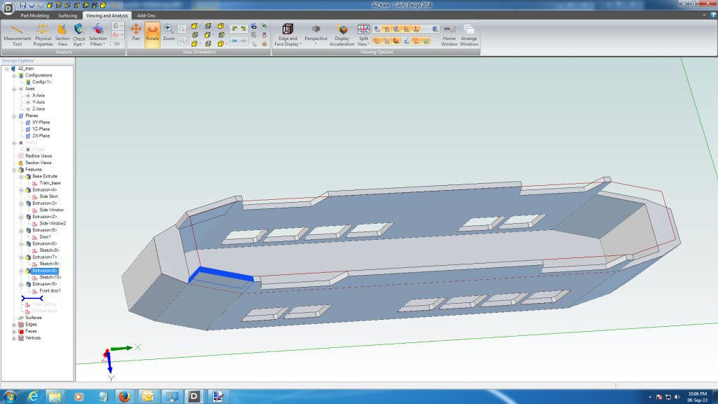
You can now select any face and draw a new sketch on it. This new sketch can then be extruded again (think of a box on a box). The sketch can also be used to cut into an existing solid, for example to hollow out the inside of the body.
To do this I selected the "underneath" face, and drew a simple box using the edge as a guide. I then used the "offset" command to make the sketch 1mm smaller all round (this will give me a 1mm "shell"), then deleted the original, closed the sketch then did a cut extrude into the body, giving a result like this.

These are the basic's, however I'm starting to build up some tricks which I plan to document further.
I have struggled with "constraints"; however, am starting to use them to good effect. I need to learn more about reference lines and how to use them as well.
The real key is that each sketch should be of a single feature (or a collection of like features, in the case above the grooves for the vertical boards) that is extruded or cut the same amount. It has taken me some time to move from the 2D world where it is all on the one drawing, a big no-no.
The real skill is trying to work out how to break down the model to allow this, and the best sequence to do it in. What I like about the parametric modeling is that you can change the order of the sequence by simply dragging and dropping the sketches and extrusions on the left had side of the work space to a new order. You can go back and edit any sketch and extrusion at any time. In this way you don't have to get it right first time but can refine the model over time.
I am having "fun" working out how to do compound curves for the celestry roof's of VR rollingstock...I'm getting closer!
Cheers
Rob